The engines that were used for propelling the early paddle steamers were of the side-lever type. In that type of engine the cylinder or cylinders were fixed vertically on the floor of the ship, a side lever being pivoted to a shaft placed low down in the vessel. Other side-wheel steamers were worked by beam engines, and as in both systems the motion of the piston rod was transmitted to the connecting rod by some kind of beam.
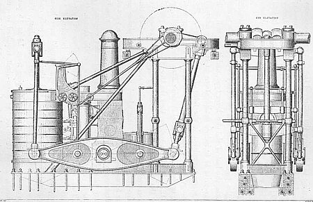
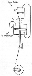
The sketch of the machinery of the S/S Arctic shows a side-lever type. The design of boilers generally used was that known as the return-flue boiler, and served its purpose until the pressures became too high for the large area of flat surfaces exposed, which were found to want considerable staying.
The pressure carried in the earlier days was so slight, that in the logbook of the S/S Britannia it was recorded on one occasion: "Broke the larboard steam-pipe, lapped it, with canvas and rope-yarn and proceeded with low pressure, meaning evidently 4 lbs. or 5 lbs. per square inch!"
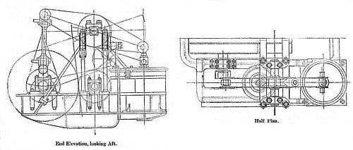
The design of the side-lever engine being fairly suitable for the paddle-wheels was generally retained down to the S/S Scotia, the last of the side-lever type, and it was still such a favorite as to induce modifications of it being retained for screw propulsion in the form of a beam-engine. The arrangement of this type is illustrated by the diagram of the engines of the Cunard steamer S/S Etna, built in 1855:
It will be noticed that the two cylinders are placed on the port side to work vertically up to the beam, the other end of which is connected to the shaft on which the spur-wheel is keyed, this wheel gears in to a pinion on the forward end of the propeller-shaft, and with a view of obtaining a good disposition of the weights, the wheels were placed between the forward and after engine, of which the forward one only is shown on the sketch.
This system of gearing for screw engines of what were then considered large power, was introduced to keep down the high piston speed which would have been required if the engines had had their piston-rods and crank-shaft connected direct to the screw-shaft, the revolutions for a side wheeler ranging from 14 to 18 per minute, whilst those for the screw-shaft required to run from 40 to 80, 90, and sometimes even 150, which was then considered much too fast for ordinary wear and tear.
COMPOUND ENGINES
Compound engines are those which have two or more cylinders of successively increasing diameters so arranged that the exhaust steam from the first and smallest cylinder is passed forward to do work in a second, and sometimes a third or fourth cylinder, before escaping to the condenser. It was invented as early as in 1845. The first transatlantic steamship fitted with compound engines was the S/S Holland of the National Line in 1869. She was re-engined with a new compound engine built by J. Jack & Co, with 2 cylinders, 1 high-pressure 46 inches diameter and 1 low-pressure of 86 inches diameter.
The compound engine enables the fullest advantage to be taken of the expansive power of high-pressure steam:
(1) By reducing the range of temperature in any one cylinder, and thereby reducing initial condensation of the steam in the cylinder.
(2) By taking advantage of the re-evaporation which accompanies cylinder condensation. For, since the bulk of the re-evaporation in a cylinder takes place during exhaust, it is obvious that in a single-cylinder engine the steam formed, by re-evaporation during exhaust passes away to the air or the condenser to waste without serving any useful purpose. When the steam is exhausted into a second or third cylinder, the steam formed by re-evaporation in one cylinder is utilized in doing useful work on the pistons of the succeeding cylinders.
(3) By the ease with which it may be adapted to work on to two or more cranks, thereby reducing the excessive variation of stress which occurs in a single-cylinder engine when working with steam at a high initial pressure expanded to a greatly reduced terminal pressure.
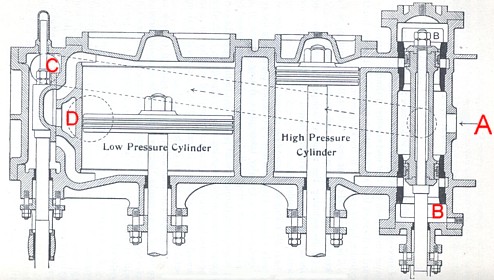
This picture (Steam, W. Ripper p.142) shows a pair of compound cylinders for a vertical engine. The steam is admitted at
A to the high-pressure cylinder. It is exhausted at
B, and carried to the low-pressure cylinder through the dotted pipe to the opening
C in the low-pressure valve chest. It is exhausted at
D to the condenser.
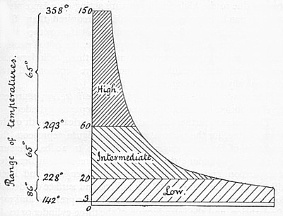
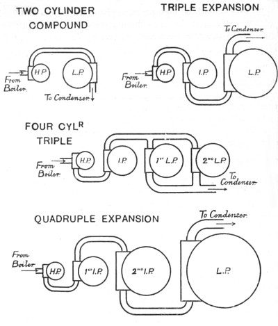
This diagram (Steam, W. Ripper p. 143) illustrates the difference between the action of the steam in a simple engine and in a triple-expansion compound engine. The engine must be made strong enough to bear the maximum stresses due to the high initial pressure acting on a large piston area, a much heavier engine would be required than if the stresses were more judiciously distributed. If now the expansion of the steam, the range of temperature, the initial stresses, and the total work are distributed among three cylinders connected with three cranks, a much more economical and mechanically perfect engine is the result. The shaded parts marked high, intermediate, low, represent the distribution of the work among three separate cylinders.
The diagram further illustrates the historical growth of the steam engine, for the bottom part of the figure represents the condition of the early engines working up to 20 lbs. pressure with a single cylinder. Then came higher pressures, higher rates of expansion, and two-cylinder compound engines, and later, with the introduction of steel for boilers, and surface condensation, we have had a rapidly increased boiler pressure and rate of expansion, and the introduction of the three-cylinder or triple expansion compound engine. Pressures are still increasing, while the terminal pressure remains constant, and a fourth cylinder is in many instances now being added, forming a quadruple expansion engine.
On a two-cylinder compound engine, the steam passes from the boiler by the steam pipe, into the valve chest of the high-pressure cylinder, where it is admitted to the cylinder and cut off at about one-half or one-third of the stroke. It is then exhausted by the pipe connecting the two cylinders, from the high-pressure into the low-pressure cylinder, where it again does work by acting on the low-pressure piston. The steam is then exhausted, either into the air or into a condenser, by a pipe. In a two-cylinder compound engine the steam exhausted from the high-pressure cylinder into the low-pressure acts as forward pressure in the low, and as back pressure in the high, and the effective work done is due to the difference in area between the two pistons.
If the pressure acts on two pistons of unequal area, the effective pressure transmitted by the pistons to the piston rod is equal to the external pressure on the small piston. The volume of the low-pressure cylinder of a compound engine required for a given power is the same as if the whole of the work to be done, and the whole of the expansions, were performed in that cylinder alone. It's size is therefore estimated as for a single-cylinder engine, to exert the required power, with the given initial pressure of steam of the high-pressure cylinder, admitted at once to the low-pressure cylinder and expanded down to the terminal pressure, the assumed point of cut-off being arranged to allow the same number of expansions as with the compound engine.
TYPES OF COMPOUND ENGINES
Compound engines may be roughly divided into two classes:
(1) those in which the pistons of each cylinder commence the stroke simultaneously. In such engines the cranks are either at 0° or 180° apart. These engines are known as the 'Woolf' type.
(2) Those in which the cranks are set at various angles other than 0° or 180°, and exhaust from one cylinder before the next cylinder is ready to receive it, in which case the steam is retained, for a portion of the stroke, in a chamber or receiver between the two cylinders. These are termed "receiver" engines.
The following are the most common arrangements of cylinders and cranks of compound engines:
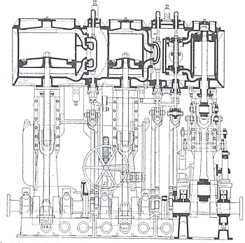
I. The Tandem Compound Engine with cylinders, as shown on the picture, the high-pressure cylinder being in line with the low-pressure cylinder, and the two pistons attached to the same piston rod. Steam is conducted from the boiler direct to the high-pressure cylinder, where it is admitted ultimately at either end of the stroke, cut off at about one-half or one-third of the stroke, expanded nearly to the end of the stroke and then exhausted into the low-pressure cylinder, where it further expands, acting as back pressure on the high-pressure piston, and forward pressure on the low-pressure piston, and is finally exhausted into the air or a condenser.
II. The Compound Engine, with the cylinders Placed side by side, and with the cranks at right angles. In this engine the steam enters the high-pressure cylinder direct from the boiler, is cut off at about one-half or one- third of the stroke, and expands to the end of the stroke of the high-pressure piston, when it is exhausted into the receiver.
Triple and quadruple expansion engines - namely, those in which the steam is expanded in three or four cylinders respectively - are the necessary outcome of increased pressures of steam; for, since the terminal pressure is about constant, increased pressures involve an increased number of expansions. And in order to prevent undue range of stress and temperature in one cylinder, three and even four cylinders are employed. Thus the same reasons which led to the rejection of the single-cylinder engine in favour of the two-cylinder compound, led to the rejection of the two-cylinder engine (at least, in marine work), and the adoption of the triple compound, and the quadruple compound, in its stead. The first transatlantic vessel with triple expansion engines, was the S/S Martello of the Wilson Line, introduced in the trade in 1884.
The economy of fuel which resulted from the introduction of high-pressure steam, and the compound engine with surface condensation for steamships, was very remarkable Between 1860 and 1870, when the pressure of steam used for marine engines was about 30 lbs. by boiler gauge, and the steam expanded in a single cylinder, the amount of coal consumed by the best engines was about 4 lbs. per I.H.P. per hour. On the introduction of the compound engine, the consumption fell to a little over 2 lbs. per I.H.P. per hour. The triple expansion engine reduced this to as low as 1.4 lbs. per I.H.P. per hour, and the quadruple expansion engine further reduced the consumption by about 10 per cent. Towards the turn of the century the four cylinder, quadruple expansion engine, appeared in several of the new express liners constructed for the transatlantic passenger trade.
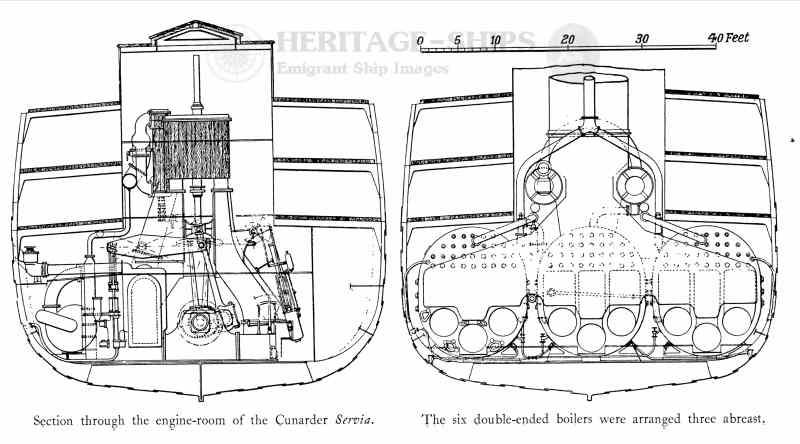
On the S/S Servia buit in 1881, the machinery consisted of two three cylinder compound surface condensing engines, each with a high pressure cylinder 72 inches diameter and two low pressure cylinders each 100 inches diameter, with a common stroke of 78 inches. There were in all seven boilers, six of which were double and one single ended, and all were made of steel, with corrugated furnaces. Steam was supplied at 90 lb. per sq. in. pressure. The total number of furnaces was thirty-nine, constructed with Fox's corrugated flues. On trial the engines indicated 10,300 horse-power, and the vessel attained a speed of 17.8 knots.