Aquitania - Cunard Line steamship, cross sectional view Support Norway Heritage: Purchase a copy |
 Aquitania - profile and deck plans Support Norway Heritage: Purchase a copy |
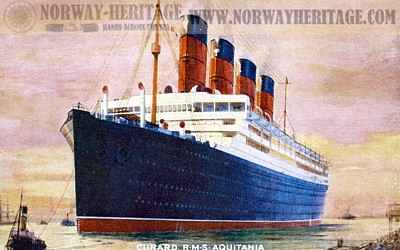
 Aquitania - on a pictue published 1914 notice the original construction of the bridge which was later reconstructed |
|
|
|
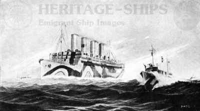
 Aquitania, Cunard Line steamship - painted for war service Support Norway Heritage: Purchase a copy |
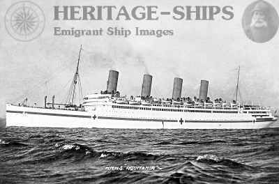
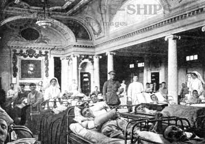
Aquitania as a hospital ship during WW1. On this image she is seen in Mudros Bay. While in Red cross service the Aquitania transported about 25,000 wounded soldiers.
Support Norway Heritage: Purchase a copy
|
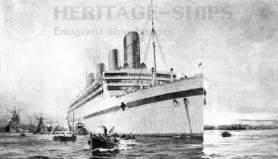
Aquitania as a troop ship during WW1. In the spring of 1918 the Aquitania carried 47,867 American soldiers to Europe in 9 voyages.
Support Norway Heritage: Purchase a copy
|
 The Aquitania's glass-enclosed promenade deck made ideal hospital wards. Support Norway Heritage: Purchase a copy |
The Aquitania's lounge concerted to Red Cross uses. All her magnificent rooms were fitted with beds.
Support Norway Heritage: Purchase a copy
|
The Cunard Liner Aquitania, built by John Brown & Company, Ltd., Clydebank, arrived in New York, June 5, on her maiden voyage. The voyage from Liverpool to Ambrose Channel Lightship, a distance of 3,181 nautical miles, was made at an average speed of 23,1 knots. Surpassing the previous Cunard express steamers Lusitania and Mauretania in every particular except speed, the Aquitania was 901 feet long overall; 97 feet beam with a molded depth of 64 feet 6 inches. With a displacement of 49,430 tons, the vessel would draw 34 feet of water, the weights being distributed approximately: Hull, 29.150 tons; machinery, 9,000 tons; bunker capacity, 6,000 tons; total dead-weight capacity, 11,280 tons. According to approximate measurements, the gross tonnage was 46,150 and the net tonnage, 17,500.
Accommodations were provided for 618 first class, 614 second class, and 1,998 third class passengers, making a total of 3,230 passengers, which, with a crew of 972, brought the total number of persons provided for on board the ship up to 4,202. The Aquitania was often referred to as "RMS Aquitania", due to the fact that she was carrying mail (RMS: Royal Mail Ship)
 Cunard steamer Aquitania, provisions required on one trip |
 Aquitania from the first to the fourth funnel |
Some of the provisions required to feed this traveling city, the giant of the Aquitania on one trip: 12,561 lbs. butter, 625 boxes of oranges, 520 boxes of apples, 29,768 lbs. sugar, 239,584 eggs, 80 tons of meat, Fowl 19,112, Ham & Bacon 15 tons, fresh fish 30 tons, 16,000 qts. claims, 1.221 qts. oysters, 1,440 gals. milk, 4,807 lbs. potatoes, 5,139 lbs. cheese, 9,450 qts. ice cream, 125 geese, 250 turkeys, 500 ducks, 3,000 fowl, 75 Heads of Cattle and Calfs, 250 Sheep and Lambs, 150 pigs, 250 pheasants, 500 pigeons, 300 grouse, 1,000 quail, 300 partridge, 250 snipe
GENERAL ARRANGEMENT
There were nine decks in the Aquitania, in addition to the hold. Of those, six were in the molded structure of the ship, and above there were three superstructure decks, the first extending for about 640 feet, the second for 624 feet, and the third, or boat deck, for about 464 feet in length amidships. Further aft, a deck house for the second class quarters was utilized for the carrying of additional boats on the same level as the boat deck proper. The total height from the keel to the boat-deck level was 94 feet.
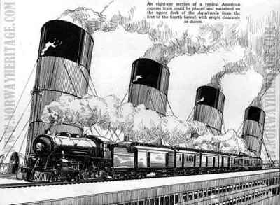
An eight-car section of a typical American express train could be placed and sustained on the upper deck of the Aquitania from the first to the fourth funnel, with ample clearance as shown DC
On the boat deck, accommodation was to be found at the forward end for the officers' quarters and mess room, and at the after end for men servants' mess room, as well as for the Marconi wireless telegraph office.
 RMS Aquitania, the boat deck |
 RMS Aquitania, first class dining saloon |
 RMS Aquitania, Garden Lounge |
 RMS Aquitania, promenade deck |
On the next deck, designated the "A" deck, the principal apartments arranged for were the first class drawing room, lounge, saloons, smoking room amidships, and a second class lounge further aft. The first class lounge and smoking room were connected by a long gallery. On either side of the first class lounge was a garden lounge.
 RMS Aquitania, swimming gymnasium |
 RMS Aquitania, theatre and cinema |
On the "B" deck there were arranged many special staterooms, with one and two beds in each. The promenade extended all round the deck house, but was screened on each side at the forward end for a considerable length by extending the bulwarks up to the "A" deck, and fitting large sliding windows. In this way it formed a sheltered promenade. On the after end of the "B" deck there was the second class smoking-room and drawing room, and the verandah cafe, outside of which there was extensive promenading space, and above which was a boat deck.
 RMS Aquitania, lounge |
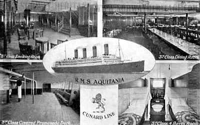 RMS Aquitania, 3rd class accommodations Support Norway Heritage: Purchase a copy |
The "C" deck, which formed the top of the molded structure of the ship, was almost entirely given over to sleeping quarters. At the forward end of that deck there was space for windlasses, capstans, cargo hatches and cargo winches, and a house enclosing the entrance to the third class quarters on the deck below. The forward part of the deck afforded a promenade for the third class passengers in fine weather. At the after end of the ship, also, there was space for working the ship with the necessary winches, capstans, and gear.
The first deck within the molded structure, designated the "D" deck, was given over largely to the cuisine department. In order to add to the comfort and simplify ventilation, the height between this and the deck above was 11 feet. The first class dining saloon was almost amidships, extending the full width of the ship. A foyer or reception room for the first class passengers was located forward of the first class dining saloon. The second class dining saloon was further aft. Between the two were the galleys. At the extreme after end of that deck there was a third class smoking room and entrance to the third class quarters, while at the forward end there was a large third class social hall.
The "E" deck was regarded as the "working deck of the ship," although the first class swimming bath and gymnasium were situated on that deck. At the after end of that deck were staterooms for second class passengers and large spaces for third class promenades. There was a passage extending right fore and aft for the use of third class, or steerage, passengers.
On "F" deck were large dining saloons for the third class passengers, while the next deck, "G," was reserved entirely for third class passengers.
 RMS Aquitania 3rd class dining saloon |
 RMS Aquitania 2 berth sleeping cabin for 3rd class passengers |
The seamen, firemen and trimmers were accommodated on several decks in the forecastle, while the stewards were berthed aft.
The ship had twenty-eight pairs of davits, consisting of both the swan-neck type and the Welin type, while among her boats were two motor lifeboats fitted with wireless telegraphy. There were in all eighty lifeboats providing ample accommodation for all people on board the ship.
INTERIOR DECORATIONS.
The restaurant in the first class accommodation measured nearly 150 feet in length and 97 feet in width; the height at the sides was 10 feet and in the center, where there was a large well 41 feet by 23 feet, the room attained a height of 19 feet; the floor area was 13,500 square feet. The decoration was in the Louis XVI style, and the woodwork was in paneled mahogany and painted grey, the whole being enriched with carved ornament and decorative paintings.
The general scheme of decoration which had been chosen for the first class lounge was that in vogue about the time of George I, and was reminiscent of the work of Sir Christopher Wren. The color scheme was wine red and vellum. The center of the room, which was 18 feet in height, was ornamented with a genuine old ceiling painting on canvas, representing an allegorical subject, and signed by Van Cuygen, a well-known decorative painter of the Dutch school. The room had large Georgian windows overlooking the garden lounge. A semicircular stage or platform was planned at one end of the room, decorated with a fine coffered vault, under which was a reproduction of the famous tapestry representing the battle of Solebay. The floor, which was of oak and suitable for dancing, was covered with a plum-colored trellis carpet, the center being a replica of a fine Savonnerie example.
The general idea in the first class smoking room was to retain a ship effect, with architectural proportions. The plan of the room generally was interesting. It was 76 feet long and 52 feet wide, with a lofty central portion and fine spacious rooms adjoining, divided off by glazed and paneled partitions, with oak carvings of nautical trophies and draperies.
The long gallery stretched for nearly 150 feet - from the first class smoking room to the lounge. On the port side large sash windows overlooked the deck promenade and the sea. The walls were paneled in mahogany and the period of decoration was about 1788, the black and grey tiling of the floor harmonizing admirably.
Stretching for a distance of nearly 150 feet on either side of the public rooms on "A" deck was the garden lounge, the surroundings of which were reminiscent of an Old English garden.
The entrance hall and main staircase, the writing rooms and the foyer or reception room, were all decorated in the Louis XVI style, while the grill room was of the early Jacobean period.
The accommodation provided for second class cabin passengers was remarkably complete, including three features which were usually only available for first class passengers - a verandah cafe, lounge and gymnasium. The public rooms were very large and the decoration, while less elaborate than in the first cabin, was worked out in a very tasteful manner.
HULL CONSTRUCTION
From bow to stern there was a double bottom, which had a depth of 5 feet 4 inches, increased to 6 feet 3 inches in the turbine room. In all there were 41 watertight compartments in the double bottom, each of which could be pumped out or filled separately. Five of the fore-and-aft girders were watertight and there were further six longitudinal intercostal girders, composed of 12/20 inch plates. The center keelson was built up of 21/20 inch plates, with double angles at top and bottom, secured to a flat keel made up of three plates of a collective thickness of 3½ inches. The seven longitudinals on each side of the center girder were 12/20 inch thick.
The frames above the margin plates were steel channels. Web frames, 36 inches deep, were introduced at every third frame throughout the greater part of the length of the ship, but closer where required, notably in the machinery space. All these extended at least to the deck 10 feet above the load waterline, and some to decks above this level.
The shell plating was 23/20 inch thick amidships, the sheer strakes being doubled and riveted by hydraulic riveters. The hull was divided into eighty-four compartments, in addition to the forty-one in the double bottom: There were sixteen transverse bulkheads, most of which extended 19 feet above the load waterline, while the others extended to 9 feet above the load waterline. The turbine room was divided into three compartments by two longitudinal bulkheads. Similarly, the condensing plant aft was divided into two units by a center line bulkhead. In order that the damage by collision at the point of junction of the transverse bulkhead in the machinery space with the shell plating should not affect two compartments a V-shaped connection had been made, so that damage at that point may be localized to one compartment only. The tunnel end of the condensing room was also divided into several compartments by the fresh water tanks.
There was a fore-and-aft bulkhead on each side of the space occupied by the boilers, extending a distance of 450 feet. The longitudinal bulkheads forming the inner walls of the bunkers were 18 feet from the outer skin of the ship. The space within the inner walls, constituting the boiler rooms, was thus 60 feet wide. In the coal-bunker space again there were fitted partial transverse bulkheads dividing these bunkers into ten watertight cellular sections on each side, varying from 27 feet to 33 feet in length.
The hatches to the cargo holds were trunked and made watertight to the weather deck. The engine and boiler casings were extra well stiffened by webs and made watertight to 20 feet above the load waterline. This, in conjunction with the making of the decks watertight, would localize the volume which could, owing to accident, be flooded. The main transverse bulkheads were of 12/20 inch plating stiffened by 12-inch channels space 2 feet 6 inches apart, and at intervals there were introduced vertical web stiffeners 3 feet deep, formed of 10/20 inch plates and double angles. In line with the two intercostal girders between the web frames at two points in the height of these vertical members, already mentioned, there were horizontal girders carried across the bulkheads at a level between the double bottom and "G" deck. All the doors below and adjacent to the load line were of the sliding pattern and were fitted with Stone-Lloyd quick-closing gear.
The anti-rolling tanks took the place of one of the coal bunkers on each side of the ship.
The top strength deck, known as "B" deck, was 73 feet from the keel plate. The shell plating was doubled for a height of 12 feet at the gunwale, while the "B" deck was single plated. Below this level there were five complete decks extending fore and aft, and distant apart vertically from 8 feet to 11 feet, the greater height being on the deck where the first and second class dining saloons and some of the staterooms were located. At the ends of the ship, forward and abaft the machinery spaces, there was a partial deck, making six within the molded structure of the ship. These decks had beams at every frame, consisting of 10-inch channels. The thickness of the deck plating varied from ¾ inch to 1 inch. Special beams were fitted in the turbine compartments in order to carry the gear for raising and lowering the upper part of the casing and the rotor. Above the molded structure of the ship there were two decks, designate the "A" deck and the boat deck. These extended 2 feet beyond each side of the molded structure, giving increased space for promenading, games and stowage of boats.
 S/S Aquitania compared in size to the Capitol |
BOILERS
Steam was supplied at a pressure of 195 pounds per square inch by twenty-one double-ended, eight-furnace Scotch boilers, each 17 feet 8 inches mean diameter and 22 feet long. The total heating surface of all the boilers was 138,595.8 square feet and the total grate surface, 3,541.8 square feet, making a ratio of heating surface to grate area of 39.1 to 1. The shell plates were 1 19/32-inch thick, the front tube plates 25/32-inch thick and the back tube plate 13/16-inch thick over the center furnaces and 7/8-inch thick over the outer furnaces. The plain tubes were of iron 2½ inches outside diameter of 8-wire gage, while the stay tubes were from 2½-inch diameter and ¼-inch thick to 2½-inch diameter by 3/8-inch thick.
The boilers were arranged in four separate boiler rooms, six boilers were arranged three abreast in each of the three forward boiler rooms; while the after boiler, room contained only three boilers. The total boiler space, including cross bunkers and auxiliary machinery rooms was 369 feet long and 6o feet wide, while the remaining space on each side from the longitudinal bulkheads to the shell of the vessel was utilized for coal bunkers. Cross bunkers were arranged between the first and second and second and third boiler rooms, while between the third and fourth boiler rooms, at the H-deck level, was the electric plant and below that an auxiliary machinery compartment.
Seven Stone's ash expellers were fitted in recesses in each boiler room. The capacity of the pumps for each expeller was approximately 4,500 tons per hour, and as those pumps could be utilized in emergency as bilge pumps their capacity added a valuable margin of safety in case of disaster.
Howden's latest system of forced draft was applied to all the boilers. Twenty-eight electrically-driven fans, located in separate fan rooms on the G-deck level, supplied the air for combustion. The fans were 66 inches diameter, designed to run at a speed of 450 revolutions per minute against a pressure of 3½ inches of water. Each pair of fans was driven by one Allen electric motor of 50 horsepower.
PROPELLING MACHINERY:
Propulsion was by Parsons turbines of approximately 56,000 horsepower arranged according to the triple expansion system on four shafts. Two longitudinal bulkheads divided the engine room into three compartments - the high-pressure ahead and the high-pressure astern turbine were in the port engine room, the intermediate-pressure ahead and another high-pressure astern turbine were in the starboard engine room, while two low-pressure ahead turbines, in which were incorporated the low-pressure astern turbines, were in the center engine room, actuating the two center shafts. Aft of the turbine rooms were the two main condensers, located in separate compartments.
The high-pressure ahead turbine was 40 feet 2 inches long overall, weighing 240 tons. The high-pressure ahead rotor drum was 9 feet 2 inches diameter, weighing about 80 tons, The drum was in two portions connected by a heavy junction wheel. There were four stages of expansion in that turbine, the blades varying from 3 3/8 inches to 7 inches long. The casing of the turbine was of cast iron. The high-pressure astern turbine, fitted abaft the high-pressure ahead turbine, was 22 feet 11 inches long, weighing 120 tons. There were four expansion stages, with blades varying from 1½ inches to 3 inches of length, while the high-pressure astern rotor drum was 7 feet 10 inches in diameter, weighing 40 tons.
The intermediate-pressure turbine was similar to the high-pressure turbine, except for the dimensions. The ahead turbine was 41 feet 6½ inches long and had four expansion stages with the blades varying from 6¾ inches to 14 inches length; the rotor drum was 10 feet 4 inches in diameter. As the astern turbine coupled with the intermediate-pressure ahead turbine was a high-pressure turbine, it was a duplicate of the high-pressure astern turbine on the port wing shaft.
The low-pressure ahead and astern turbines on the inner shafts, which were incorporated in the same casings, were 54 feet 3 inches long with rotor drums 12 and 10 feet in diameter respectively. There were nine expansion stages in the ahead turbines and four in the astern turbines. The blades in the former ranged from 7 to 20 inches in length and in the latter from 5 to 7 inches. The ahead and astern drums were connected by a cast steel ring, while the ahead drum, which was in two sections, had a junction wheel of cast steel similar to that used in the high-pressure and intermediate-pressure turbines. Motor-driven gear was arranged for lifting the casings and rotors of the turbines, lifting motors of 30 brake horsepower operating lifting screws through worm gearing.
The high-pressure turbines in the wing compartments were placed well forward, while the low-pressure turbines were placed aft close to the main condensers. At the after end of the wing compartments were located the evaporating plant, auxiliary pumps and the auxiliary condensers. At the forward end of the center turbine room were located the main feed, sanitary and forced lubrication pumps. Forced lubrication was supplied to all the turbine bearings as well as to the tunnel shaft bearings. For the latter, six direct acting Weir pumps, 12½ by 10 by 24 inches were required, four being used to maintain the oil supply.
The two main condensers were of Weir's uniflux type, constructed by Messrs. John Brown & Company, Ltd., each had 23,000 square feet of cooling surface, and the circulation was on the double-flow system. The main circulating pumps supplied by Messrs W. H. Allen, Son & Company, Ltd., were four in number arranged in two pairs. The steam cylinders were 14 inches in diameter by 10½ inches stroke, each engine capable of delivering 18,500 gallons of water per minute against a total suction and delivery head of 31 feet 6 inches, the speed being 350 revolutions per minute. Each condenser was supplied with two sets of Weir dual air pumps, the air cylinders being 38 inches diameter by 21 inches stroke, each driven by a steam cylinder 20 inches diameter by 21 inches stroke.
The exhaust from the auxiliaries and the turbo electric plant was led to auxiliary condensers at the forward end of each wing turbine room. The auxiliary condensers were of Weir's unflux type with 2,000 square feet of cooling surface each. The circulating pumps supplied by Messrs. Allen delivered 2,500 gallons of water per minute against a 20-foot head when running at a speed of 330 revolutions. The air pumps of Weir's monotype design had air cylinders 24 inches diameter and steam cylinders 12 inches diameter, both with a 15 inch stroke.
AUXILIARIES
Three pairs of Weir's standard feed pumps, supplemented by a duplicate installation of auxiliary feed pumps, were located at the forward end of the center turbine room. The pumps had water cylinders, 13 inches diameter and steam cylinders 18½ inches diameter by 27 inches stroke. Four Weir Hotwell pumps, 14 inches by 12 inches by 26 inches stroke, were located in each condenser room, each pump being capable of delivering the feed water for 14,000 shaft horsepower. Four Harris feed water filters arranged in pairs on each side of the center turbine room were supplied and two Weir uniflux surface feed heaters, each with a heating surface of 1,000 square feet, capable of dealing with the feed water for 28,000 shaft horsepower. Other pumps in the central turbine room included a vertical duplex 11-inch by 10-inch by 10-inch sanitary pump and a similar one for deck and fire purposes with a capacity of 200 tons per hour and three pumps for the Stone-Lloyd watertight door system.
Ventilation of the machinery compartments was accomplished by the plenum system, the fan equipment for which consisted of nineteen motor-driven Keith-Blacktnan supply and exhaust fans with an aggregate capacity of 660,000 cubic feet of air per minute. The refrigerating plant, installed for the preservation of the ship's stores, was of the carbonic-anhydride type, manufactured by the Liverpool Refrigeration Company, Ltd., Liverpool. For ventilating the passenger quarters the thermo-tank system had been adopted, the installation consisting of about 100 units electrically operated.
THE ELECTRIC PLANT
Electricity was supplied by four 400 kilowatt 1,500 revolutions per minute 225-volt direct-current turbo generating sets of the British Westinghouse type, located on the G-deck, between the second and third boiler rooms, while an emergency set, consisting of a 45-brake horsepower Diesel engine, supplied by Messrs. Mirrlees, Bickerton & Day, coupled to a Westinghouse 30-kilowatt generator, was located on the promenade deck for emergency purposes. Current was supplied for about 180 motors aggregating over 2,000 horsepower, and for about 10,000 lamps.
 Aquitania with the rebuilt elevated bridgehouse Support Norway Heritage: Purchase a copy |
 Aquitania, with the rebuilt elevated bridgehouse Support Norway Heritage: Purchase a copy |
 S/S Aquitania of the Cunard Line in New York Harbour |
 S/S Aquitania at the landing stage, Liverpool Support Norway Heritage: Purchase a copy |
[International Marine Engineering, 1914]
Cunard Line image gallery