The Titanic was of the same design as her sister the
Olympic and had ten decks, named from the bottom upwards: Lower orlop, orlop, lower, middle, upper, saloon shelter, bridge, promenade and boat deck. The passenger decks were the promenade deck, bridge deck, shelter deck, saloon deck, tipper deck, middle deck and lower deck. They were named alphabetically A, B, C, D, E, F, and G. Two of the decks were above the molded structure of the ship. The lower orlop, orlop and lower decks did not extend for the complete length of the structure and was interrupted for the machinery accommodation. The bridge deck extended for a length of 550 feet amidships, the forecastle and poop on the same level was respectively 128 feet and 106 feet long. The promenade and boat decks were also over 500 feet long. The first class passengers were accommodated on the five levels from the upper to the promenade decks. The second class passengers had their accommodation on the middle, upper and saloon decks, and the third class passengers on the lower deck, forward and aft, and on the middle, upper and saloon decks aft. There were three elevators in the main companionway and one in the main second class companionway. For first class passengers there were thirty suite rooms on the bridge deck and thirty-nine on the shelter deck. They were so arranged that they could be let in groups to form suites including bedrooms, with baths, etc., with communicating doors. On each of these two decks, close to the companionways on either side, adjacent rooms were fitted up as sitting or dining room. In all there were nearly 330 first class rooms, and 100 of these were single-berth rooms. There was accommodation for over 750 first class passengers.
For second class passengers the rooms were arranged as two or four-berth rooms, the total number of second class passengers were over 550. For the third class passengers there was a large number of enclosed berths, there were 84 two-berth rooms. The total number of third class passengers provided for was over 1,000.
The first class promenades on the three top decks in the ship were exceptionally fine. The bridge deck promenade was entirely enclosed. It was a space over 400 feet long, 13 feet minimum width each side of the vessel, and with a solid side screen fitted with large, square lowering windows. The deck above this was the principal promenade deck, and was entirely devoted to first class passengers. It was more than 500 feet long, and formed a splendid promenade, the width in parts exceeded 30 feet. The topmost, or boat deck, was also devoted to first class promenading, and was 200 feet long and the full width of the ship. The first class dining saloon was designed to accommodate 532 passengers, and ample smoke-room, restaurant, lounge and reading and writing room accommodation was also provided.
The second class dining saloon was situated on the saloon deck aft. It extended the full breadth of the vessel, with extra large opening pivoted sidelights arranged in pairs. The paneling of the room was carried out in oak. The third class dining accommodation was situated amidships on the middle deck, and consisted of two saloons well lighted with sidelights and was finished enamel white.
The Titanic was a triple-screw steamer and had a combination of reciprocating engines with a low-pressure turbine. The reciprocating engines exhausted into the low-pressure turbine, which drove the central propeller. The reciprocating engines which drove the wing propellers were sufficient for maneuvering in and out of port and going astern. There was no necessity for an astern turbine, which was required in steamers fitted with turbines only. There were 29 boilers for the ship, and in all 159 furnaces. All of the boilers were 15 feet 9 inches in diameter. 24 were double-ended, 20 feet long, while 5 were single-ended, 11 feet 9 inches long. The shells of the latter were formed by one plate, the others had three strakes. At each end there were three furnaces, all of the Morison type, with an inside diameter of 3 feet 9 inches. The working pressure was 215 pounds under natural draft. The boilers were arranged in six watertight compartments, and owing to the width of the ship it was possible to fit five boilers athwartship. The boiler compartment nearest the machinery space accommodated the single-ended boilers, and those were arranged for running the auxiliary machinery while the ship was in port, as well as for the general steam supply when the ship was at sea.
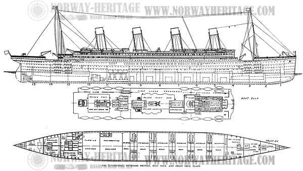
Titanic, outboard profile, boat deck and orlop deck plans.
Support Norway Heritage: Purchase a copy
In each of the five large boiler rooms there were two See's ash ejectors, and in addition there were four of Railton & Campbell's ash hoists for use when the vessel was in port. A large duplex pump of Harland & Wolff's own make was fitted in a separate room in each boiler room, the advantage being that the working parts of the pumps were not injuriously affected by dust. The boilers were fitted with the Ross-Schofield patent marine boiler circulators. The exhaust turbine, instead of being in the same engine room with the two sets of piston engines, as in earlier ships, was accommodated in a separate compartment abaft the main reciprocating engine room, and divided from it by a watertight bulkhead. In the reciprocating engine room there were two sets of main engines — one driving the port and the other the starboard shaft. In the wings were the main feed and hot-well, bilge, sanitary, ballast and fresh-water pumps, and a contact and surface heater. On the port side a space had been found for an extensive refrigerating plant under the immediate observation of the engineers.
The two sets of reciprocating engines — one driving each wing shaft — were of the four-crank type, arranged to work at 215 pounds per square inch, and to exhaust at a pressure of about 9 pounds absolute. Those engines were on the balanced principle. The high-pressure cylinder was 54 inches in diameter, intermediate cylinder 84 inches, and each of the two low-pressure cylinders 97 inches in diameter, the stroke was 75 inches in all cases. The exhaust steam turbine, by which the central screw was driven, was of the Parsons type, to take exhaust steam at about 9 pounds absolute and expand it down to 1 pound absolute. The condensing plant was designed to attain a vacuum of 28½ inches (with the barometer at 30 inches), the temperature of circulating water was 55 degrees to 60 degrees F. The rotor was built up of steel forgings, and was 12 feet in diameter. The blades ranged in length from 18 inches to 25½ inches, built on the segmental principle, laced on wire through the blades and distance pieces at the roots, and with binding soldered on the edge. The length of the rotor between the extreme edges of the first and last ring of blades was 13 feet 8 inches.
There was no astern turbine, as the center shaft was put out of action when the ship was being maneuvered. The bearings, thrust and governor were of the ordinary type adopted in Parsons turbines. The turbine could be rotated by electric motor, and the usual lifting gear for the upper half of the casing and the rotor was also actuated by electric motor. The rotor weight was about 130 tons, and the turbine complete weight was 420 tons. The turbine shaft was 20½ inches in diameter, the tail shaft 22½ inches, each with a 10-inch hole bored through it.
The propeller driven by the turbine was built solid, of manganese bronze with four blades, the diameter was 16 feet 6 inches. It was designed to run at 165 revolutions per minute when the power developed was 16,000 shaft-horsepower. The inlet of the turbine condensers was of the full length of the condenser, and was well stayed vertically by division plates. In line with those there were in the condenser corresponding division plates, which secured an equal distribution of steam over the whole of the condenser tube area. The pear shape concentrated the tube surface at the point where the largest volume of steam was admitted where it was most needed.
There were four sets of gunmetal circulating pumps, two for the port and two for the starboard condensers, with 29-inch inlet pipes and driven by compound engines of Harland & Wolff's own make. For each condenser there were two sets of Weir's air pumps of the "dual" type, both air and water barrels 36 inches in diameter by 21 inches stroke.
For generating electric current, both for light and power, four 400-kilowatt engines and dynamos were fitted in a separate watertight compartment aft of the turbine room at tank-top level. The engines, which indicated each about 580 horsepower, were of the Allen vertical three-crank compound, enclosed forced lubrication type, running at 325 revolutions per minute. Each set had one high-pressure cylinder, 17 inches in diameter, and two low-pressure cylinders, each 20 inches in diameter, with a 13-inch stroke. They took steam at 185 pounds pressure per square inch. The engines exhausted either into a surface heater or to the condenser. Each engine was direct-coupled to a compound-wound, continuous-current dynamo, with an output of 100 volts and 4,000 amperes. Their collective capacity was 16,000 amperes. The dynamos were of the ten-pole type, and were fitted with inter-poles.
In addition to the four main generating sets there were two 30-kilowatt engines and dynamos, placed in a recess off the turbine room at saloon-deck level. Three sets could be supplied with steam from either of several boiler rooms, and were available for emergency purposes. They were similar to the main sets, but the engines were of the two-crank type. The distribution of current was effected on the single-wire system, and was controlled and metered at a main switchboard placed on a gallery in the electric engine room, to which the main dynamo cables and feeders were connected. The latter passed up through port and starboard cable trunks to the various decks, radiating from thence to master switch and fuse boxes grouped at convenient points in the machinery spaces and accommodation. From there branches ran to the distribution fuse boxes scattered throughout the vessel controlling the lamps and motors.
A complete system of electric lighting was provided, and electricity was also largely employed for heating as well as for motive power, including seventy-five motor-driven "Sirocco" fans, from 55 inches to 20 inches in diameter, for ventilating all the passenger and crew spaces as well as the engine and boiler rooms. All the fan motors were provided with automatic and hand-speed regulation.
The shell plating of the ship was remarkably heavy. It was mostly of plates 6 feet wide and of about 30 feet in length. The width tapered towards the ends. The laps were treble-riveted, and the shell strakes in the way of the shelter and boat decks had been hydraulically riveted. Also the turn of the bilge, where bilge keels 25 inches deep, were fitted for 295 feet of the length of the vessel amidships. There were fifteen transverse watertight bulkheads, extending from the double bottom to the upper deck at the forward end of the ship, and to the saloon deck at the after end far above the load waterline. The room in which the reciprocating engines were fitted was the largest of the watertight, compartments, and was about 69 feet long; while the turbine room was 57 feet long. The boiler rooms were generally 57 feet long, with the exception of that nearest the reciprocating engine compartment. The holds were 50 feet long. Any two compartments could be flooded without in any way involving the safety of the ship. The two decks forming the superstructure of the ship and the navigating bridge were built to ensure a high degree of rigidity. At the sides they were supported on built-up frames, in line with the hull frames, but at wider intervals. The deck houses were specially stiffened by channel-section steel fitted in the framework. Where the public rooms pierced the deck, heavy brackets were introduced to increase strength against racking stresses when the ship was steaming through a heavy seaway. Expansion joints were made in the superstructure above the bridge deck at convenient points in the length — one forward and one aft, the whole structure was completely severed and the joints suitably covered.
The stern-frame was made by the Darlington Forge Company, and the total weight of the casting was about 190 tons, the stern frame 70 tons, the side propeller brackets 73¼ tons, and the forward boss-arms 45 tons. The center propeller, driven by the turbine, worked in the stern-frame aperture, while the wing propellers were supported in brackets. The stern frame was of Siemens-Martin mild cast steel, of hollow or dish section, in two pieces, with large seraphs, one on the forward post and one on the after post, connected with best "Lowmoor" iron rivets, 2 inches in diameter, the total weight of rivets was over a ton. They were all turned and fitted and specially closed with rams. There were in all 59 rivets in the forward and 54 rivets in the after seraphs. In the stern frame was the boss for the shaft driven by the turbine, the lower portion of this part of the stern frame had a large palm cast on its extreme forward end, to give a solid connection to the after boss-arms and main structure of the vessel.
The rudder also had been constructed by the Darlington Forge Company, Ltd., and was of the elliptical type, of solid cast steel, built in five sections, coupled together with bolts varying from 3½ inches to 2 inches in diameter. The top section of the rudder was of forged steel from a special ingot of the same quality as naval gun jackets. On the completion of the forging an inspection hole was bored through the stock of the rudder in order to ensure that there were no flaws.
The steering gear was fitted on the shelter deck, and was very massive, the diameter of the rudder stock - 23½ inches — affording some idea of the dimensions. The gear was of Harland & Wolff's wheel-and-pinion type, working through a spring quadrant on the rudder head, with two independent engines, with triple cylinders, one on each side. Either engine could be used for the working of the gear, the other being a stand-by. The gear was controlled from the navigating bridge by telemotors and from the docking bridge aft by mechanical means.
The navigating appliances included, in addition to two compasses on the captain's bridge and one on the docking bridge aft, a standard compass on an isolated brass-work platform in the center of the ship, at a height of 12 feet above all iron work and 78 feet above the waterline. Adjacent to the bridge there were two electrically-driven sounding machines, arranged with spars to enable soundings to be taken when the ship was going at a good speed.
The vessel was fitted with complete installation for receiving submarine signals. The lifeboats, which were 30 feet long, were mounted on special davits on the boat deck. The ship was designed for two masts, 205 feet above the average draft line, a height necessary to take the Marconi aerial wires, and to insure that they were at least 50 feet above the top of the funnels and thus clear of the funnel gases. The masts were also for working the cargo by means of cargo spans, and in addition there was on the foremasts a derrick for lifting motor cars, which could be accommodated in one of the fore-holds. There were three cargo hatches forward and three aft. All the hatches in the after part of the ship were served by electric cranes of the same make; two of them were on the promenade deck where there were two small hatches to the hold below, so as to form a minimum of interference with the promenading space.

Titanic, launch.
The general arrangements for launching the 45,000-ton White Star steamship Titanic, which occurred on May 21, 1911 at the Harland & Wolff shipyard at Belfast, were similar to those in the case of the sister ship Olympic. The vessel was held on the ways by hydraulic triggers, only requiring to be released by the opening of a valve in order to let her glide into the water. Her launching time was 62 seconds, her speed 12 knots and her weight about 25,000 tons.
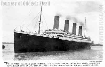
While traveling at full speed on her maiden trip from Southampton to New York at 11:40 P. M. (ship's time), Sunday, April 14, the Titanic collided with an iceberg at a point west longitude 50° 14', north latitude 41° 46', or about 1,150 miles east of New York. Less than three hours later the ship sank, carrying with her all on board except about 700 persons who were taken off in lifeboats and later picked up by the
Carpathia of the
Cunard Line. As the total number of persons on board the Titanic was 2,340, including officers and crew, the loss of life was about 1,600. The vessel was certified by the British Board of Trade to carry over 3,300 persons, but the certificate provided for only sufficient lifeboats to carry 950 persons.
Titanic leading dimensions:
Length over all: 882 ft. 9 ins.
Length between perpendiculars: 850 ft.
Breadth, extreme: 92 ft. 6 ins.
Depth, molded, keel to top of beam, bridge deck: 73 ft. 6 ins.
Total height from keel to navigating bridge: 104 ft.
Gross tonnage (about): 45,000 tons.
Load draft: 34 ft. 6 ins,
Displacement (about): 60,000 tons.
Indicated horsepower of reciprocating engines: 30,000
Shaft horsepower of turbine engines: 16,000
Speed : 21 knots.